Transport protocol
The data between the PC and STM is Protobuf preceeded by a 7-byte header and 5+n byte header.
The header itself consists of the following bytes:
| Description | Amount of bytes | Value |
|---|---|---|
| Start bytes | 1 | 0x2 |
| Sender receiver | 1 | 0x0* |
| Message ID | 1 | 0x0 |
| Size of content | 2 | number of bytes in content |
| Checksum of content | 1 | checksum of content (everything after 7th byte) |
| Checksum of header | 1 | checksum of header (first 6 bytes, skipping the leading 0x2) |
Sender receiver
The sender-receiver value is documented as follows
Enums
| Value | Description |
|---|---|
| PC | 0 |
| nRF | 1 |
| STM | 2 |
| STM - Memory | 3 |
Left 4 bits represent a sender Right 4 bits represent a recipient
STM - Memory has been separated for memory operations (Import, Export), due to ease of implementation.
The content consists of the following bytes:
| Description | Amount of bytes | Value |
|---|---|---|
| Protobuf Structure ID | 2 | Structure ID |
| Type | 1 | 12 |
Size of Protobuf content | 2 | number of bytes in the Protobuf content |
Protobuf content | n | The Protobuf content that's being sent |
Checksum
The message checksum is calculated by summing all bytes together and overflowing at a byte (sum % 256).
Structure ID
These structures are connected to the ones accessible here.
| Structure | ID |
|---|---|
Command | 0x10 |
Project | 0x11 |
Station | 0x12 |
Test | 0x13 |
Measurement | 0x14 |
RESERVED | 0x15 |
Result | 0x16 |
Setting | 0x17 |
Ota | 0x18 |
TesterInfo | 0x19 |
OtaInfo | 0x20 |
ExportCommand | 0x21 |
ImportCommand | 0x22 |
Communication enums
To include the communication enums starting with C_G_ into your own project, you can visit our public repository for them.
Then simply include the files and use them.
Fixed enums
There are a few enums that are fixed and aren't generated
OTA
Commands
| enum | number |
|---|---|
OTA | 100 |
Parameters
| enum | number |
|---|---|
Init | 101 |
OtaErase | 102 |
ShowUpdatePopup | 103 |
ShowTransferInProgressPopup | 104 |
ShowTransferCompletedPopup | 105 |
Responses
| enum | number |
|---|---|
OK | 150 |
N_OK | 151 |
Tester info
Commands
| enum | number |
|---|---|
TesterInfo | 200 |
End
Commands
| enum | number |
|---|---|
End | 400 |
Import/Export
Commands
| enum | number |
|---|---|
Import | 300 |
Export | 301 |
Parameters
| enum | number |
|---|---|
Project | 350 |
Station | 351 |
Test | 352 |
Measurement | 353 |
Communication
The communication is based on Google's Protocol Buffer protocol, which generates code at build time.
The protocol schema is defined inside of a schema (*.proto) file, which is used to statically generate code and structures needed to serialize and deserialize bytes.
CLI Tool
ProtoBuf provides a CLI tool, called protoc, which can be used to generate the code and inspect the generated packets.
Code generation
To generate the code using the protoc tool, you will first need a schema.
Schema
A simple schema can be something like this:
message Example {
    int32 id = 1;
}
Which would, after the code generation, create an object that contains a single varint.
Code generation
To generate the code from the above schema, you will have to save it into a file, for this example test.proto, and run:
$ mkdir csharp
$ protoc test.proto --csharp_out=csharp/
Which should result in a new file, located at csharp/Test.cs, with code that can serialize and deserialize packets.
Printing binary contents
To figure out what is in the binary file generated from the program, you can use the following command:
$ protoc --decode Test --proto_path=. test.proto < test.bin
Which should result in:
id: 1
Schema
The schema that's used in the Hamilton communication is the following:
syntax = "proto3";

message Command {
    int32 command = 1;
    optional int32 parameter = 2;
    optional string filter = 3;
}

message Project {
    UID project_id = 10;
    int32 seq_num = 11;
    int32 client_code = 12;
    int32 site_code = 13;
    repeated Result results = 14;
    optional int32 last_update = 15;
    optional string name = 16;
}

message Station {
    UID station_id = 20;
    int32 seq_num = 21;
    repeated Setting settings = 22;
    UID project_id = 23;
    repeated Result results = 24;
    float earth_bond_limit_connection_point_1 = 25;
    optional float earth_bond_limit_connection_point_2 = 26;
    repeated float earth_bond_limit_test_point = 27;
    optional int32 last_update = 28;
    repeated int32 mfts_used = 29;
    bool marked_for_deletion = 30;
    optional float loop_line_limit = 31;
    optional string name = 32;
}

message Test {
    UID test_id = 30;
    int32 test_type = 31;
    int32 station_part = 32;
    int32 last_update = 33;
    repeated Result results = 34;
    UID station_id = 35;
}

message Measurement {
    UID measurement_id = 40;
    repeated Setting settings = 41;
    repeated Result results = 42;
    optional Graph graph = 43;
    UID test_id = 44;
}

message Graph {
    bytes byte_array = 50;
}

message Result {
    int32 name_enum = 60;
    optional string limit_low = 61;
    optional string limit_high = 62;
    optional float raw_numeric_value = 63;
    optional int32 enum_value = 64;
    int32 evaluation = 65;
    optional int32 unit = 66;
    optional int32 user_forced_state = 67;
    optional string rendered_numeric_value = 68;
}

message Setting {
    int32 name_enum = 70;
    optional float float_value = 71;
    optional int32 enum_value = 72;
}

message Ota {
    int32 seq_num = 80;
    int32 address = 81;
    bytes byte_array = 82;
}

message UID {
    int32 serial_counter = 90;
    int32 timestamp = 91;
}

message TesterInfo {
    string fw_stm = 100;
    string fw_bt = 101;
    string protocol_version = 102;
    int32 serial_number = 103;
    string model = 104;
    int32 last_calibration_date = 105;
}

message OtaInfo {
    int32 number_of_packets = 110;
    int32 overall_crc32 = 111;
    string firmware_version = 112;
}

message UpdatePacket {
    OtaInfo info = 120;
    repeated Ota packets = 121;
}

message ExportCommand {
    int32 parameter = 130;
    optional UID project = 131;
    optional UID station = 132;
    optional UID test = 133;
    optional UID measurement = 134;
}

message ImportCommand {
    int32 parameter = 130;
    optional UID project = 131;
    optional UID station = 132;
    optional UID test = 133;
    optional UID measurement = 134;
}
Database entries
The database consists of different tables, which connect with one to many relations. The relations are specified using a "parent id" on the children elements.
UID
UID is a structure storing instrument serial number and a timestamp, thus providing a unique identifier
| Field | Type |
|---|---|
| instrument_serial | int32 |
| timestamp | int32 |
The instrument_serial field doesn't use first 5 bits, so we use them as a counter.
The counter helps us when data is saved multiple times in a single second.
The timestamp field is in seconds since EPOCH (01-01-1970).
Project
Project is a top-level structure, which stores a name and code.
| Field | Type |
|---|---|
| Project ID | UID |
| Sequence number | int32 |
| Client code | int32 |
| Site code | int32 |
| Results | [Result] |
| Time of last update | int32 |
Station
Station is a structure that specifies the station being tested.
| Field | Type |
|---|---|
| Station ID | UID |
| Sequence number | int32 |
| Settings | [Setting] |
| Project ID | UID |
| Results | [Result] |
| Earth bond limit connection point 1 | float |
| Earth bond limit connection point 2 | optional float |
| Earth bond limit test points | [float] |
| Time of last update | int32 |
| MFTs used | [int32] |
| Marked for deletion | bool |
Test
Test is a structure that specifies a group of measurements that can be repeated.
| Field | Type |
|---|---|
| Test ID | UID |
| Test type | int32 |
| Station part | int32 |
| Time of last update | int32 |
| Results | [Result] |
| Station ID | UID |
Measurement
Measurement is a structure that contains Results.
| Field | Type |
|---|---|
| Measurement ID | UID |
| Settings | [Setting] |
| Results | [Result] |
| Graph | optional Graph |
| Test ID | UID |
Graph
Graph is a structure that holds bytes that can be shown inside of the graph widget on the Hamilton.
| Field | Type |
|---|---|
| Byte_Array | byte_array |
Result
Result is a structure that holds a value, limit and evaluation of the result. Value can be an integer, float or an enum, so it's returned as a string.
| Field | Type |
|---|---|
| Name enum | int32 |
| Limit | optional string |
| Numeric value | optional string |
| Enum value | optional int32 |
| Evaluation | int32 |
| Unit | optional int32 |
| User forced state | optional int32 |
Setting
| Field | Type |
|---|---|
| Name enum | int32 |
| Numeric value | optional string |
| Enum value | optional int32 |
Command
The command structure is made of multiple parameters, of which only one is mandatory.
| Field | Type | Optional |
|---|---|---|
| Command | int32 | FALSE |
| Parameter | int32 | TRUE |
| Filter | string | TRUE |
Command field
The command field can contain an enum from the below table.
| Enum | Value |
|---|---|
Ota | 100 |
Ok | 150 |
Nok | 151 |
TesterInfo | 200 |
Import | 300 |
Export | 301 |
End | 400 |
DateTime | 500 |
Parameter field
The parameter field can contain an enum from the below table
| Enum | Value |
|---|---|
Start | 101 |
OtaErase | 102 |
ShowUpdatePopup | 103 |
ShowTransferInProgressPopup | 104 |
ShowTransferCompletedPopup | 105 |
Project | 350 |
Station | 351 |
Test | 352 |
Measurement | 353 |
Filter field
The filter field can be a UNIX time integer to set the Hamilton time using DateTime command.
Export command
The ExportCommand is a structure that contains path to the information it wants to export and a property that explains what type you're looking for.
| Field | Type |
|---|---|
| parameter | int32 |
| project | UID |
| station | UID |
| test | UID |
| measurement | UID |
Import command
The ImportCommand is a structure that contains path to the information it wants to import and a property that explains what type you're looking for. It needs to include the UID of the imported object
| Field | Type |
|---|---|
| parameter | int32 |
| project | UID |
| station | UID |
| test | UID |
| measurement | UID |
Ota message
Ota is a structure that holds values needed for OTA update.
| Field | Type |
|---|---|
| sequence number | int32 |
| address | int32 |
| byte_array | byte_array |
Tester info
Tester info is the response to command TesterInfo.
| Field | Type |
|---|---|
| Firmware STM | string |
| Firmware nRF | string |
| Protocol version | string |
| Serial number | int32 |
| Model | string |
| Last calibration date | int32 |
OtaInfo message
OtaInfo is a structure that holds values needed for OTA update.
| Field | Type |
|---|---|
| number of packets | int32 |
| overall crc32 | int32 |
| firmware_version | string |
OTA Update
STM Update
STM can update itself through OTA. It will flash itself through IAP and after verifying the flashed data, it will restart into the new application.
OTA has a few communication enums that can be passed into the Command message:
| Command | Parameter | Description |
|---|---|---|
Ota | OtaErase | Erases the flash and prepares for flashing |
Ota | ShowUpdatePopup | Shows the update popup that notifies the user that an update is underway |
Ota | Start | Tells the instrument that the update will follow |
OtaErase should be sent if the instrument returned 0 in the Ok after the OtaInfo packet.
If there are some packets present on the instrument, we should skip that many packets and continue from where it was last.
ShowUpdatePopup should be sent before a device starts updating and should be sent for both nRF and STM updates. The popup hides when the End is sent at the end of update.
OtaInfo contains a field overall_crc32, which should be compared with the last update that was done, so that we can track if there are some packets of this update already present or not.
OTA has a message called OTA with three fields:
| Field | Description |
|---|---|
seq_num | Number of the packet in the update procedure |
address | The location the bytes will be written to |
byte_array | The bytes to be written |
OTAInfo has a message called OTAInfo with three fields:
| Field | Description |
|---|---|
number_of_packets | Number of all packets in the update procedure |
overall_crc32 | CRC32 calculated over the whole binary |
firmware_version | Version of the new firmware |
OTA also reuses the global End command:
| Command | Parameter | Description |
|---|---|---|
End | Finish the update |
After the End command is sent, the STM verifies the flashed parts of the flash, switches to the new application and reboots.
If the overall checksum doesn't match, it returns N_OK and shows a popup, otherwise it returns OK and reboots.
Replies
Commands OtaErase, Start and End will reply with OK or N_OK commands depending on the status of the command that was executed last.
STM Update procedure

nRF Communication
The nRF communication for transferring data contains a service with UID 0x1000 which contains two characteristics:
| Characteristic | ID |
|---|---|
| Write | 0x6000 |
| Notification | 0x7000 |
The data received and sent on these characteristics, is in Protobuf protocol.
nRF Commands
The nRF communication protocol defines commands
| Commands | Value | Description | Direction (to) |
|---|---|---|---|
C_G_PAIR | true/false | Start/stop pairing process on nRF. | nRF |
C_G_PAIRED | Serial number of MFT | Returns when the MFT has been paired. | STM |
C_G_CONNECTED | No value | Returns when the MFT has connected. | STM |
C_G_DISCONNECTED | No value | Returns when the MFT has disconnected. | STM |
C_G_ROLE | Role values | Change the Bluetooth role. | nRF |
C_G_MAC | MAC address | Provides the MAC address of the bonded device | both |
C_G_FIRMWARE | The version of nRF | Returns the FW version of nRF (eg. "00.65") | STM |
C_G_EXPORT_BUFFERS_READY | No value | Tells STM that the Export buffers are ready to receive data | STM |
- The
C_G_MACshould always be sent with theC_G_CENTRALrole command. - The
C_G_MACis also sent withC_G_PAIREDin the direction of STM. - The
C_G_FIRMWAREis sent after thenRFandSTMare handshaked.
Role values
Possible values for role:
| Value | Description |
|---|---|
C_G_IDLE | Put nRF into idle, to conserve power |
C_G_CENTRAL | Put nRF into MFT connectivity mode |
C_G_PERIPHERAL | Put nRF into PC connectivity mode |
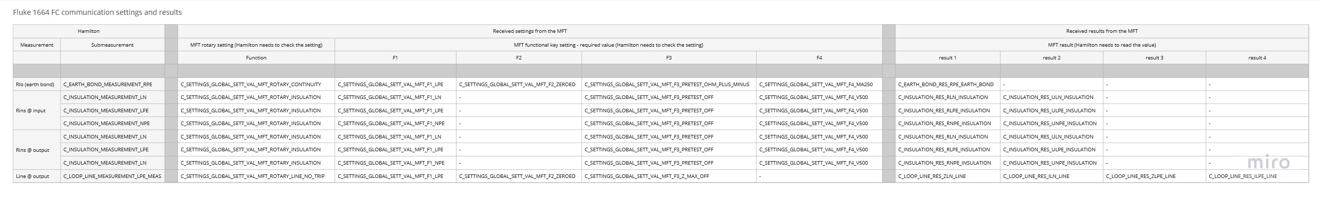
MFT Communication
Communication is through common_com_lib, which allows us to add multiple items and specify key-value entries.
MFT Schema
Commands
The MFT communication protocol defines 4 MFT commands
| Commands | Value | Description |
|---|---|---|
C_G_EVENT_ENTER | Enter values | Enter into the measurement |
C_G_EVENT_START | Start values | Start sending the results |
C_G_EVENT_STOP | No value | Stop sending the results |
C_G_EVENT_EXIT | No value | Exit from the measurement |
Enter values
C_G_EVENT_ENTER command has to specify the measurement we want to enter.
Possible values for Earth Bond measurement:
| Value | Description |
|---|---|
C_EARTH_BOND_MEASUREMENT_RPE | Earth bond measurement |
Possible values for Insulation measurement:
| Value | Description |
|---|---|
C_LOOP_LINE_MEASUREMENT_LN_MEAS | Voltage measurement between L1 and N |
C_LOOP_LINE_MEASUREMENT_LPE_MEAS | Voltage measurement between L1 and PE |
C_LOOP_LINE_MEASUREMENT_NPE_MEAS | Voltage measurement between N and PE |
Possible values for Line measurement:
| Value | Description |
|---|---|
C_LOOP_LINE_MEASUREMENT_LN_MEAS | Voltage measurement between L1 and N |
C_LOOP_LINE_MEASUREMENT_LPE_MEAS | Voltage measurement between L1 and PE |
Start values
C_G_EVENT_START command has to specify the measurement we want to enter.
Values are the same as they are for C_G_EVENT_ENTER.
Settings
There are 5 different settings that can be set.
C_SETTINGS_GLOBAL_SETT_MFT_ROTARYC_SETTINGS_GLOBAL_SETT_MFT_F1C_SETTINGS_GLOBAL_SETT_MFT_F2C_SETTINGS_GLOBAL_SETT_MFT_F3C_SETTINGS_GLOBAL_SETT_MFT_F4
Rotary values
Rotary tells us which measurement is selected on MFT using rotary selector.
| Value | Description |
|---|---|
C_SETTINGS_GLOBAL_SETT_VAL_MFT_ROTARY_INSULATION | Insulation measurement is selected |
C_SETTINGS_GLOBAL_SETT_VAL_MFT_ROTARY_CONTINUITY | Continuity measurement is selected |
C_SETTINGS_GLOBAL_SETT_VAL_MFT_ROTARY_LINE_NO_TRIP | Line no trip measurement is selected |
C_SETTINGS_GLOBAL_SETT_VAL_MFT_ROTARY_NA | None of the above measurements is selected |
F1 values
Possible values for the F1 setting.
| Value | Description |
|---|---|
C_SETTINGS_GLOBAL_SETT_VAL_MFT_F1_LN | Measurement between L and N sockets |
C_SETTINGS_GLOBAL_SETT_VAL_MFT_F1_LPE | Measurement between L and PE sockets |
C_SETTINGS_GLOBAL_SETT_VAL_MFT_F1_NPE | Measurement between N and PE sockets |
C_SETTINGS_GLOBAL_SETT_VAL_MFT_F1_NA | F1 is set to none of the above |
F2 values
Possible values for the F2 setting.
| Value | Description |
|---|---|
C_SETTINGS_GLOBAL_SETT_VAL_MFT_F2_ZEROED | The result value had been zeroed already |
C_SETTINGS_GLOBAL_SETT_VAL_MFT_F2_NA | F2 is set to none of the above |
F3 values
Possible values for the F3 setting.
| Value | Description |
|---|---|
C_SETTINGS_GLOBAL_SETT_VAL_MFT_F3_PRETEST_OFF | |
C_SETTINGS_GLOBAL_SETT_VAL_MFT_F3_PRETEST_OHM_PLUS_MINUS | |
C_SETTINGS_GLOBAL_SETT_VAL_MFT_F3_Z_MAX_OFF | |
C_SETTINGS_GLOBAL_SETT_VAL_MFT_F3_NA | F3 is set to none of the above |
F4 values
Possible values for the F4 setting.
| Value | Description |
|---|---|
C_SETTINGS_GLOBAL_SETT_VAL_MFT_F4_MA250 | |
C_SETTINGS_GLOBAL_SETT_VAL_MFT_F4_V500 | |
C_SETTINGS_GLOBAL_SETT_VAL_MFT_F4_NA | F4 is set to none of the above |
Results
Results are always of type FLOAT.
The message sent over the communication, should consist of keys specified below, according to the measurement, and value, which will always be a float.
RPE Earth bond
RPE Earth bond only has one result.
| Result |
|---|
C_EARTH_BOND_RES_RPE_EARTH_BOND |
Insulation
Insulation contains 6 results.
| Result |
|---|
C_INSULATION_RES_RLN_INSULATION |
C_INSULATION_RES_ULN_INSULATION |
C_INSULATION_RES_RLPE_INSULATION |
C_INSULATION_RES_ULPE_INSULATION |
C_INSULATION_RES_RNPE_INSULATION |
C_INSULATION_RES_UNPE_INSULATION |
Line
Line measurement contains 4 results.
| Result |
|---|
C_LOOP_LINE_RES_ZLN_LINE |
C_LOOP_LINE_RES_ILN_LINE |
C_LOOP_LINE_RES_ZLPE_LINE |
C_LOOP_LINE_RES_ILPE_LINE |
Measurement procedure

The measurement procedure is as follows:
- Selection of the measurement using
Enter- After the
Enteris called, the MFT settings will be sent to the STM initially and after a change.
- After the
- Start of the result sending using
Start- After the
Startis called, the MFT results will be sent to the STM everynmilliseconds. - If we're still in
Enter, settings can still be received if they change.
- After the
- Stop the sending of results using
Stop - Exit the measurement using
Exit
Example
The following is an example of how the communication should be executed.
The packets will be in JSON for readability, but should be in the common_com_lib packets in practice.
- Send an
ENTERcommand withC_EARTH_BOND_MEASUREMENT_RPEmeasurement.
STM -> nRF1
{
  "items": [
    {
      "key": "C_G_EVENT_ENTER",
      "value": "C_EARTH_BOND_MEASUREMENT_RPE"
    }
  ]
}
- The
nRFshould start sending back currentMFT's settings, preferrably when their value has changed.
nRF -> STM2
{
  "items": [
    {
      "key": "C_G_FUNC_SETTINGS_GLOBAL"
    },
    {
      "key": "C_SETTINGS_GLOBAL_SETT_MFT_ROTARY",
      "value": "C_SETTINGS_GLOBAL_SETT_VAL_MFT_ROTARY_CONTINUITY"
    },
    {
      "key": "C_SETTINGS_GLOBAL_SETT_MFT_F1",
      "value": "C_SETTINGS_GLOBAL_SETT_VAL_MFT_F1_LN"
    },
    {
      "key": "C_SETTINGS_GLOBAL_SETT_MFT_F2",
      "value": "C_SETTINGS_GLOBAL_SETT_VAL_MFT_F2_ZEROED"
    },
    {
      "key": "C_SETTINGS_GLOBAL_SETT_MFT_F3",
      "value": "C_SETTINGS_GLOBAL_SETT_VAL_MFT_F3_PRETEST_OHM_PLUS_MINUS"
    },
    {
      "key": "C_SETTINGS_GLOBAL_SETT_MFT_F4",
      "value": "C_SETTINGS_GLOBAL_SETT_VAL_MFT_F4_MA250"
    }
  ]
}
- When the measurement on
STMis started, theC_G_EVENT_STARTwill be sent.
STM -> nRF3
{
  "items": [
    {
      "key": "C_G_EVENT_START",
      "value": "C_EARTH_BOND_MEASUREMENT_RPE"
    }
  ]
}
- The
nRFshould start sending back results when they're available, possibly waiting for the user to start the measurement.
nRF -> STM4
{
  "items": [
    {
      "key": "C_EARTH_BOND_MEASUREMENT_RPE"
    },
    {
      "key": "C_EARTH_BOND_RES_RPE_EARTH_BOND",
      "value": 0.25
    }
  ]
}
- The
STMstops the measurement.
STM -> nRF5
{
  "items": [
    {
      "key": "C_G_EVENT_STOP",
      "value": null,
    }
  ]
}
- The
STMexits the measurement.
STM -> nRF6
{
  "items": [
    {
      "key": "C_G_EVENT_EXIT",
      "value": null,
    }
  ]
}
Packets templates in C/C++
To create the packet, the following boilerplate can be used:
Enter packet
MSG_CREATE(msg);
MSG_APPEND(msg, C_G_EVENT_ENTER, C_EARTH_BOND_MEASUREMENT_RPE);
MSG_SEND(&comm, msg);
Settings packet
MSG_CREATE(msg);
MSG_APPEND(msg, C_G_FUNC_SETTINGS_GLOBAL);
MSG_APPEND(msg, C_SETTINGS_GLOBAL_SETT_MFT_ROTARY, C_SETTINGS_GLOBAL_SETT_VAL_ROTARY_INSULATION);
MSG_APPEND(msg, C_SETTINGS_GLOBAL_SETT_MFT_F1, C_SETTINGS_GLOBAL_SETT_VAL_MFT_F1_LN);
MSG_APPEND(msg, C_SETTINGS_GLOBAL_SETT_MFT_F2, C_SETTINGS_GLOBAL_SETT_VAL_MFT_F2_ZEROED);
MSG_APPEND(msg, C_SETTINGS_GLOBAL_SETT_MFT_F3, C_SETTINGS_GLOBAL_SETT_VAL_MFT_F3_PRETEST_OHM_PLUS_MINUS);
MSG_APPEND(msg, C_SETTINGS_GLOBAL_SETT_MFT_F4, C_SETTINGS_GLOBAL_SETT_VAL_MFT_F4_MA250);
MSG_SEND(&comm, msg);
Start packet
MSG_CREATE(msg);
MSG_APPEND(msg, C_G_EVENT_START, C_EARTH_BOND_MEASUREMENT_RPE);
MSG_SEND(&comm, msg);
Result packet
MSG_CREATE(msg);
MSG_APPEND(msg, C_EARTH_BOND_MEASUREMENT_RPE);
MSG_APPEND(msg, C_EARTH_BOND_RES_RPE_EARTH_BOND, 0.25);
MSG_SEND(&comm, msg);
Stop packet
MSG_CREATE(msg);
MSG_APPEND(msg, C_G_EVENT_STOP);
MSG_SEND(&comm, msg);
Exit packet
MSG_CREATE(msg);
MSG_APPEND(msg, C_G_EVENT_EXIT);
MSG_SEND(&comm, msg);
Calibration
Calibration mode is used to calibrate the instrument and verify that the instrument works correctly.
Bluetooth specifications
To connect to the calibration part of the Hamilton, you need to connect to service with UUID 0x1337 that contains two characteristics:
| Characteristic | ID |
|---|---|
| Write | 0x3000 |
| Notification | 0x5000 |
The calibration uses the calibration protocol defined here
Data processing
nRF forwards the data received as a string on the Write characteristic and forwards it as a packet with an item ID of 666 to the STM, where it gets processed.
When sending data, nRF receives a packet that contains only one item (with an id of 666), which contains a byte array (an array of ASCII characters), which gets extracted and forwarded through bluetooth notification.